RIAA Phono Preamplifier
module from LC Audio
Most modern high quality amplifiers do not include a RIAA
Phono stage, nessescary to use a record player for input. And in the few
amps that does have a built-in RIAA, one would often see it is of a very
poor quality. Probably constructed with a cheap operational amplifier,
and some standard disc capacitors.
But why use a turntable with an expensive cartridge, just
to leave the signal amplification to this low-quality RIAA circuitry? The
answer to this question is, Don't !
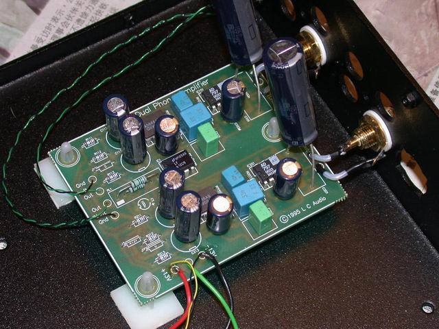
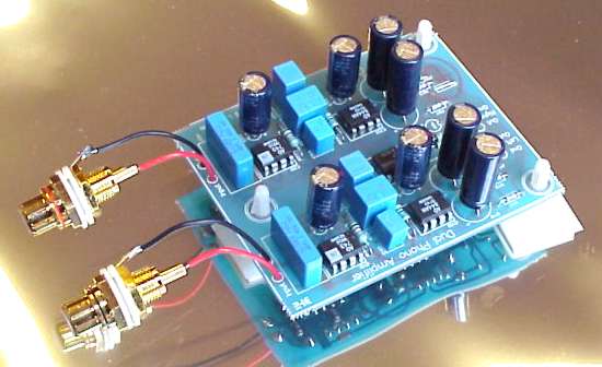
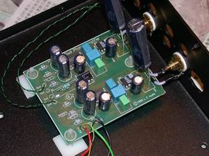
We constructed this state-of-the-art RIAA module, with
the purpose of building it into a separate case with RCA plugs, or into
an existing preamplifier or even the turntable itself, if possible.
This RIAA phono preamplifier is intended for use with
cartridges of the Moving Magnet type. If You have a Moving Magnet type,
we recommend using a suitable step-up transformer or amplifier, such as
our own top-of-the-line MC96 stage.
The technical construction of this RIAA preamp is very
advanced! It uses a passive correction with non feedback circuit to ensure
perfect sound quality. The most noise-free operational amplifiers in the
world (AD743 from Analog Devices) are utilized, to make sure You can not
hear any noise at music intersections.
The whole amplifier is - except for the very front end
- DC coupled, so no capacitor is in the signal path, apart from the one
we placed in the input circuit for protecting Your cartidge if a power
supply fault should occur.
And this one is a high grade polypropylene type from
Siemens.
 Noise Considerations
We think the issue of noise is very important when constructing
RIAA stages. Between the music pieces, there should be nothing but complete
silence. Therefore we have searched the market for ultra-low noise operational
amplifiers. The quietest bipolar operational amplifier, has an equivalent
input voltage noise of 0,9 nV/SHz, which is close to the practical measurement
limit of today's technology.
A normal metal film resistor of 75 Ohms makes more noise,
than this, due to the molecular (Brownian) Movements in the resistance
layer.
However this data is the only the voltage noise, and
since the input load from the cartridge is a very high impedance, the current
noise should also be taken into account. In this device we found the current
noise to be some 2 pA ( Pico Ampere or 0,000000000002 Ampere ). Multiplied
by the 47000 Ohms load impedance, the resulting voltage noise increases
to about 100 nV/SHz, which is way over the acceptable limit.
However using a special FET input amplifier, from Analog
Devices can solve the problem.
This device, AD743, has a voltage noise of 2,9 nV/SHz,
which is higher than the 0,9 nV, but the current noise is extremely low!
Just 7 fA/SHz ( or 350 times lower than the bipolar device ) gives us a
current inducted noise of 329 pV. This means that the 2,9 nV Voltage noise
is dominant, and a total very low level of noise.
The AD743 is coupled as a 10 times linear amplifier with
no frequency correction. After this stage the AD844 Current feedback amplifier
is used to make another 40 times amplification, a passive frequncy correction,
with no feedback, and last a signal buffering.
The special thing about this IC is that it is very fast,
and it has a compensation pin (pin 5) which can be used to reduce the open
loop gain right down to zero. Coupling pin 5 to a RIAA compensation network,
running the high frequncies to ground, results in a perfect RIAA frequency
compensation, with a maximum of musical sound performance, since no feedback
loops are used at all.
Using a Battery Power Supply
Many DIY people have asked us, if it was possible to
use a battery power supply. Therefore we have specified the power source
at + / - 13 Volts, to enable use of two simple lead accumulators. This
does not mean that we endorce the use of battery power supply, because
we have taken every measure to ensure that a normal power supply will result
in very high grade sound quality. We just felt that since a number of people
were interested in the battery issue, we should make it possible to use
it. However there is a problem with this, if the positive battery ( having
the heaviest load ) runs out of power before the negative, and no recharging
is applied.
In this case the result could be several volts of negative
DC voltage coming out of the RIAA stage, that could destroy the next amplifier
stages or loudspeakers. To avoid this we have included a small safety circuit,
that breaks the output signal with a relay, if the positive voltage is
below 10 Volts.
Normally the relay circuit is not used, since using any
mains-based power supply systems do not create DC problems, it is beneficial
to short the relay with a couple of low-ohmic resistors, just to remove
the relay contacts from the signal path.
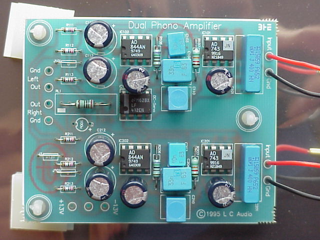 Here it is shown how the relay is shorted with two 200 Ohms
resistors.
Here it is shown how the relay is shorted with two 200 Ohms
resistors.
Only top-grade Panasonic low-ESR High Frequency electrolytic
capacitors are used for supply-rail bypassing.
The RIAA network consist of Roederstein 1% Polypropylene
capacitors and ROHM low distorsion resistors.
IMPORTANT! When connecting a battery power supply, You
should first apply a normal power supply, since the IC's could be damaged
from having only positive or negative supply at the moment of connection.
Technical Data
Signal / noise ratio 88 dB (A) 47k
Distorsion THD <0,1% 20-20.000 Hz
Frequency Response 16-100.000 Hz ( Inverse RIAA correction
)
DC offset out (max) 1 mV
Power Supply +/- 12 - 18 V
Supply Current + 40 mA - 30 mA
Application Guide
1) RIAA Phono Amplifier Module - for MM cartriges
2) RIAA Amp. with spec. opamp for MC - for high output
(0,3 to 0,7mVrms) MC cartriges
3) RIAA Phono Amplifier Module + MC Stepup Amp. w/ Optical
Supply - for low output MC cartriges
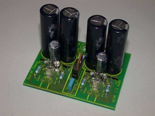
 MC
Stepup Amp. w/ Optical Supply MC
Stepup Amp. w/ Optical Supply
We did not provide load shifting for this MC stepup Amp
because our step up amplifier works in another way than a normal MC amplifier.
The MC cartridge generates a current signal, as it reads the tracks from
the LP. Normally this current signal is made into a stable voltage signal
by loading with a resistor, of various size, and then amplifying the resulting
voltage signal by maybe 25 times. This is the normal way of doing it.
Our MC step up, works in another way, it directly reads
the currents from the MC cartridge, and converts them into a voltage signal
at the output. This shortens the signal path, and reduces thermal noise.
The input impedance is near to 0, actually around 2,5 Ohms.
Assembly instruction
The RIAA module is a kit, and You should therefore assemble
it using a soldering iron, and a few normal tools.
The procedure is the normal one: Start with the low components,
and finish with the higher ones. The IC's should be fitted last, assuring
they fit in the PC board in the right direction (with pin 1 in the marked
position). The electrolytic capacitors should be turned with the minus
pin in the marked hole in the PCB. The assembly is quite simple, and the
module is easy to get to function. Remember to use a screened case, to
avoid humming. Connect case to gnd on the RIAA amplifier.
Click here for more LC Audio products
|